
Custom Coaxial Cable Assembly Products & Precision Interconnect Solutions
- Prototype Options from 1 Piece
- Typical Sampling Around 2 Weeks
- Bulk Production Around 3–4 Weeks
- 30 Engineering Personnel
- 56 Quality Personnel
- OEM & ODM Customization
- Project-Specific Quality Inspection

Explore Our Complete Coaxial Cable Assembly Product Range
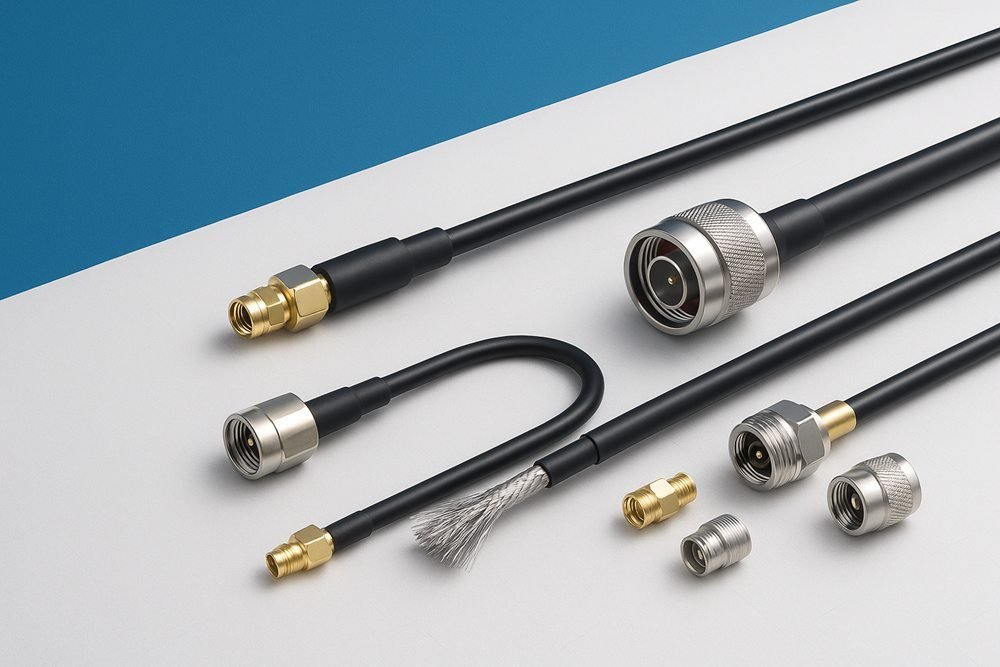
50Ω RF Coaxial Assemblies
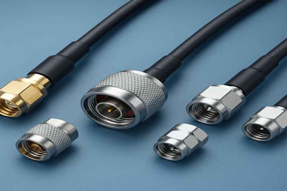
75Ω Video Coaxial Assemblies
Micro Coaxial Cable Assemblies
Low-Loss Flexible Coaxial Assemblies
Semi-Rigid Coaxial Cable Assemblies
Multi-Coaxial Cable Assemblies
Discover Coaxial Cable Assemblies Through Product Construction
RF Flexible Coax
Low-Loss Flexible Coax
Semi-Flexible Coax
Semi-Rigid Coax
Micro Coaxial Cable
Multi-Coaxial Cable
Select Coaxial Cable Assemblies by Impedance and Signal Application
50Ω RF Interconnection Systems
- System impedance: Confirm the equipment’s specified 50Ω interface rather than relying on connector appearance.
- Operating frequency: Identify the frequency range and required RF performance.
- Cable construction: Compare flexible, low-loss, micro coax and semi-rigid options according to installation conditions.
- Connector interfaces: Confirm both connector part numbers, genders, orientations and termination compatibility.
- Validation: Select continuity, insulation and applicable VSWR, return loss, insertion loss or TDR testing.
75Ω Video and Broadcast Systems
- Signal interface: Confirm the required 75Ω system impedance.
- Cable selection: Review the specified cable series, outer diameter and shielding construction.
- Connector configuration: Check BNC or F-Type part numbers, gender and termination requirements.
- Mechanical arrangement: Confirm length, routing, connector orientation and mounting conditions.
- Inspection: Verify termination dimensions, shielding integrity and electrical continuity.
Compare Coaxial Cable Series and Material Constructions
RG Series Coax
LMR-Class Coax
Micro Coax Construction
PTFE Coaxial Cable
Semi-Rigid Copper-Tube Coax
Choose Coaxial Assembly Configurations for Equipment Interfaces
Straight-to-Straight Assemblies
Straight-to-Right-Angle Assemblies
Right-Angle Connector Assemblies
Bulkhead Coaxial Assemblies
Panel-Mount Coaxial Assemblies
Mixed-Connector Assemblies
Connector Compatibility and Coaxial Interface Solutions
| Connector Family | Representative Types | Engineering Review |
|---|---|---|
| Threaded RF | SMA, N-Type, TNC | Thread interface, gender, impedance, frequency and cable termination |
| Bayonet RF | BNC | 50Ω or 75Ω system requirement, connector specification and mating interface |
| Snap-On RF | SMB, MCX, MMCX | Connector dimensions, mating structure and cable compatibility |
| Micro Coax | U.FL | Board-side interface, cable outer diameter and miniature termination |
| Video Interfaces | BNC, F-Type | 75Ω system requirements and equipment-side mating configuration |
| High-Frequency RF | SMP, SMPM, QMA, 2.92mm | Connector series, frequency requirement, geometry and termination method |
Key Technical Specifications for Coaxial Cable Selection
System Impedance
Operating Frequency
Signal Loss
Shielding Effectiveness
Cable Outer Diameter
Minimum Bend Radius
Cable Length and Tolerance
Connector Orientation and Environment
Coaxial Cable Assembly Manufacturing for Different Equipment Industries
OEM Equipment Manufacturers
RF Equipment Manufacturers
Telecom Equipment Manufacturers
Antenna and GNSS Manufacturers
Broadcast Equipment Manufacturers
Test Instrument Manufacturers
Medical Equipment Manufacturers
Machine Vision Equipment Manufacturers
Automotive Electronics Suppliers
Embedded Electronics Designers
EMS Providers
Contract Manufacturers and Integrators
Coaxial Cable Assembly Applications Across Eight Industries
RF Communication Systems
Broadcast and Video Equipment
RF Test and Measurement Instruments
Antenna and GNSS Systems
Medical Equipment
Machine Vision and Industrial Cameras
Customize Coaxial Cable Assemblies Around Equipment Requirements
Impedance and Frequency
Cable Family Selection
Connector Part Numbers
Mixed-End Interfaces
Cable Length and Tolerance
Connector Orientation
Bulkhead and Panel Mounting
Shielding Configuration
Jacket and Material Choice
Waterproof and Protection
Labeling and Identification
Low-Loss and Multi-Coax Builds
Select the Right OEM and ODM Development Model
Drawing-Based OEM
Specification-Based OEM
Sample-Based Development
Photo-Led Feasibility Review
ODM Engineering Collaboration
Prototype-to-Production Transfer
Develop Coaxial Cable Prototypes Before Production Release
Review Equipment Interfaces and Engineering Information
Prototype development begins with a review of the available technical information. Sino-Media can work from approved drawings, BOMs, connector datasheets, samples or equipment interface photographs. The review identifies the specified impedance, operating frequency, cable series, connector part numbers, finished length and required orientation. If important information is missing, the engineering team identifies the items requiring confirmation before selecting materials or preparing the sample.
Engineering inputs:
- Drawing revision and BOM information.
- Connector manufacturer and complete part numbers.
- Required cable type, outer diameter and length.
- Impedance, frequency and applicable loss requirements.
- Installation routing, bend radius and environmental conditions.
- Required electrical and RF testing.
Feasibility review: Connector availability, cable sourcing, termination method, tooling requirements and test arrangements are considered before confirming the development route.
For projects involving mixed connectors or miniature interfaces, both cable ends should be reviewed separately. Physical mating compatibility, cable termination suitability and electrical requirements are independent checks. Resolving them before prototype production helps avoid unnecessary changes after the first sample has been assembled.
Confirm Cable Construction and Connector Termination
Once the interface requirements are understood, Sino-Media reviews the suitable cable and connector construction. The selection process considers electrical requirements, mechanical dimensions and manufacturing feasibility. A flexible RF cable, micro coax or semi-rigid construction may require different preparation and termination arrangements, so the product family should be confirmed before work instructions are released.
Cable and connector selection:
- Confirm the exact cable series and material specification.
- Check outer diameter against connector termination requirements.
- Review the center conductor, dielectric and shielding structure.
- Confirm straight, right-angle or mixed-end connector arrangements.
- Identify any bulkhead, panel mounting or protective requirements.
- Define the required cable length and dimensional references.
Termination definition: The assembly drawing should identify stripping dimensions, conductor positioning, shielding preparation and connector orientation. For semi-rigid products, forming geometry and bend locations also require confirmation.
A representative sample or approved connector drawing helps establish the correct interface. If special connectors or custom cable materials are required, sourcing availability must be considered when confirming the sample schedule. The prototype should be manufactured against the agreed engineering information rather than assumptions based on connector appearance.
Manufacture, Test and Approve the Prototype
After the engineering definition is confirmed, Sino-Media prepares the prototype using the agreed cable, connectors and termination method. The sample is inspected for cable length, connector positioning, stripping dimensions, center conductor alignment and shielding integrity. Basic electrical checks include continuity and insulation testing, while additional RF measurements are selected according to the project specification.
Sample timing reference:
- Engineering validation can start from 1 piece when required connectors and materials are available.
- Standard or in-stock samples usually require 2–3 working days.
- Custom-developed samples usually require 5–10 working days.
These periods refer to sample preparation under suitable material and engineering conditions. Special connector sourcing, custom cable requirements, tooling, complex tests and approval activities can affect the actual schedule.
Approval and production transfer: The approved sample, drawing revision, BOM and test requirements become the reference for subsequent manufacturing. Any change to cable construction, connector part number or termination method should be reviewed and approved before production release.
CTA: Start Prototype Development
Factory and Manufacturing Capability for Coaxial Cable Assemblies
Engineering Release Connects Drawings With Manufacturing
- Confirm the current drawing and BOM revisions.
- Verify connector and cable specifications.
- Check material availability and approved alternatives.
- Confirm termination tooling and production fixtures.
- Define work instructions and inspection requirements.
- Establish the applicable electrical and RF test plan.
Cable Preparation and Precision Coaxial Termination
Assembly Resources, Tooling and Process Control
- Cable cutting and stripping operations.
- Connector crimping and soldering processes where applicable.
- Shielding and protective processing.
- Assembly fixtures and product-specific tooling.
- Inspection and electrical testing resources.
- Controlled work instructions and operating procedures.
Quality Control and Electrical Testing for Coaxial Cable Assemblies
| Quality Stage / Test | Inspection or Measurement | Purpose |
|---|---|---|
| Incoming Material Inspection | Cable specifications, connector part numbers and material identification | Confirm supplied materials match the approved BOM |
| Cable Preparation Inspection | Cutting length, stripping dimensions, dielectric and shield condition | Prevent damage or incorrect preparation |
| Connector Termination Inspection | Center conductor position, crimping or soldering and connector seating | Verify termination quality and interface construction |
| Dimensional Inspection | Finished length, connector orientation and assembly geometry | Confirm mechanical fit against the drawing |
| Continuity Test | Electrical connection through the specified path | Identify open circuits and connection interruptions |
| Insulation Test | Insulation performance under the specified test conditions | Identify insulation-related electrical issues |
| RF Performance Testing | VSWR, return loss, insertion loss or TDR where required | Evaluate specified RF characteristics |
| Final Inspection | Appearance, identification, packaging and required records | Confirm finished-product release requirements |
Certifications and Compliance for Coaxial Cable Manufacturing
Quality Management Systems
Environmental and Occupational Safety
Medical Quality Management
Automotive Quality Management
Product and Material Compliance
Manufacturing and Acceptance Standards
- Applicable management-system certificates.
- UL material or component records where relevant.
- RoHS and REACH material declarations.
- Project-specific inspection and test reports.
- Certificate of Conformity (COC).
- First Article Inspection (FAI).
- PPAP and IMDS documentation where required.
Typical Coaxial Cable Assembly Configurations for Equipment
50Ω RF Jumper Assembly
75Ω Video Cable Assembly
Micro Coax Board-Level Assembly
Semi-Rigid RF Jumper Assembly
Low-Loss Flexible Coax Assembly
Multi-Coax Integrated Assembly
Coaxial Cable Assembly Engineering Scenarios
German RF Test Equipment Program
- Market: Germany
- Equipment profile: RF test instrument manufacturer
- Product: 50Ω RF coaxial cable assembly
- Illustrative planning quantity: 1,000 pcs
- Cooperation model: Drawing-based OEM
United States Medical Imaging Program
- Market: United States
- Equipment profile: Medical imaging equipment developer
- Product: Micro coaxial cable assembly
- Illustrative planning quantity: 1,000 pcs
- Cooperation model: ODM engineering collaboration
Japanese Broadcast Equipment Program
- Market: Japan
- Equipment profile: Broadcast video equipment manufacturer
- Product: 75Ω video coaxial cable assembly
- Illustrative planning quantity: 1,000 pcs
- Cooperation model: Specification-based OEM
Plan MOQ, Production Lead Time and Repeat Orders
Prototype Quantities and OEM ODM Production MOQ
- Engineering prototype: From 1 piece when materials and connectors are available.
- Regular OEM production MOQ: Typically 100 pcs.
- Regular ODM production MOQ: Typically 1,000 pcs.
Production Scheduling and Delivery Lead Time
- Small-batch or standard structures: Usually 5–7 working days.
- Large or fully customized projects: Usually 10–25 working days.
Repeat Orders and Long-Term Supply Planning
- Confirm the current drawing and BOM revision.
- Recheck material and connector availability.
- Verify tooling and fixture readiness.
- Review work instructions and inspection requirements.
- Confirm first-article or pilot requirements when applicable.
- Align packaging, labels and shipment instructions.
Frequently Asked Questions About Coaxial Cable Assemblies
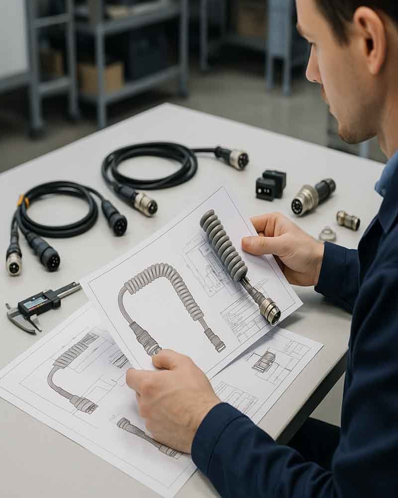
Send Your Coaxial Cable Assembly Requirements to Sino-Media
- Cable type, impedance, frequency and outer diameter.
- Connector manufacturer, part number, gender and orientation.
- Cable length, tolerance, bend radius and routing conditions.
- Drawing, BOM, pinout, sample or reference photographs.
- Prototype quantity, OEM or ODM production quantity and estimated annual demand.
- Required continuity, insulation and RF testing.
- Target delivery date and applicable compliance requirements.